DESN 132B — PERSP & RENDERING SYSTEMS II | SPR 2020 | M/W 1:00–3:45PM | HSD105
TUTORIALS & HOW-TO GUIDES
STUDENT EXAMPLES
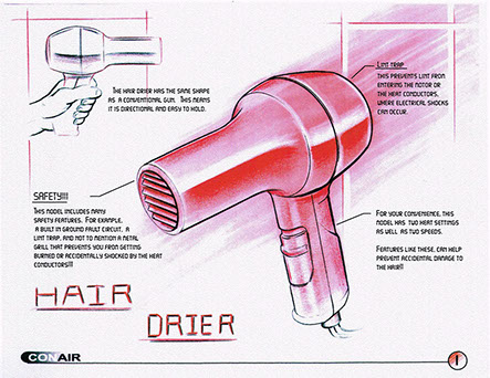

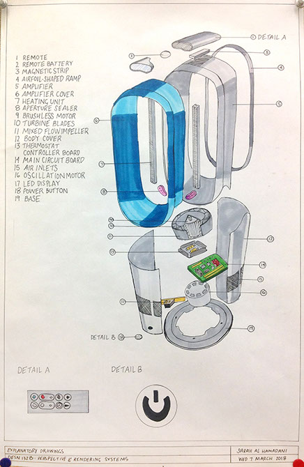
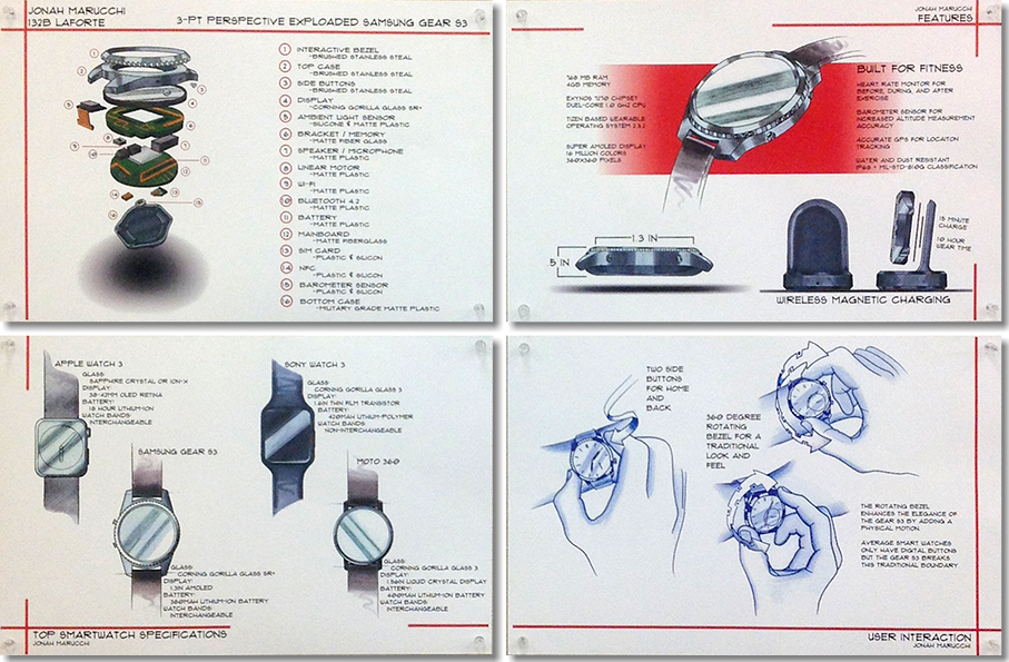
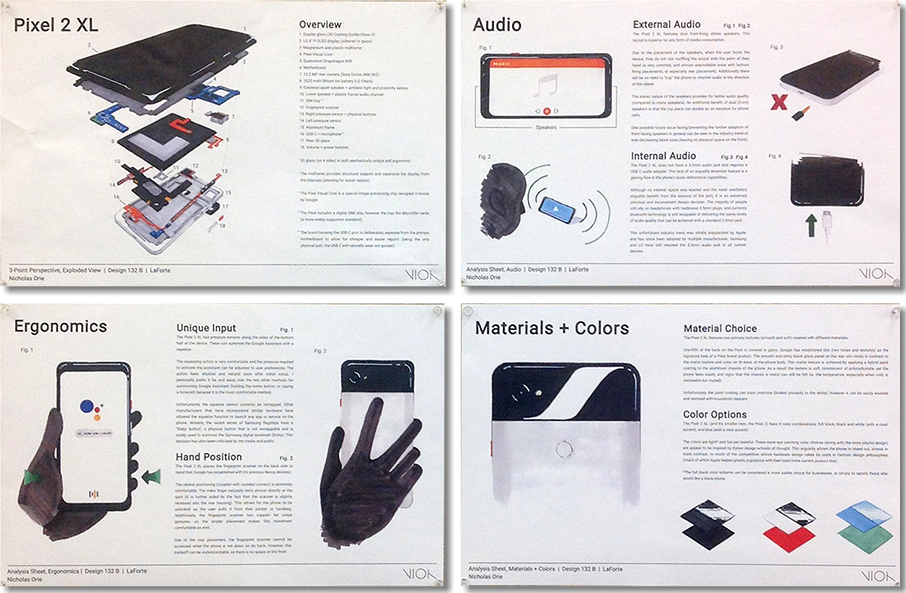

STUDENT EXAMPLES
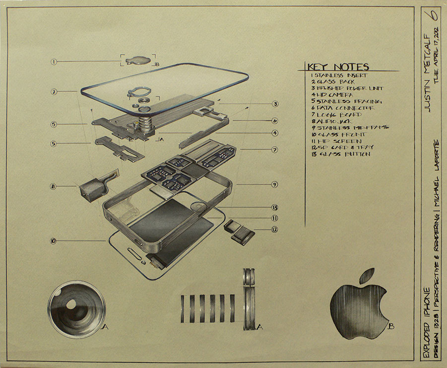
Part 1 base construction and rough layout study of an iPhone 4 series by student, Justin Metcalf.
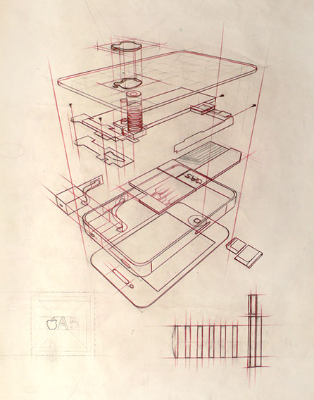

Part 2, finished rendering on Canson by student, Justin Metcalf.
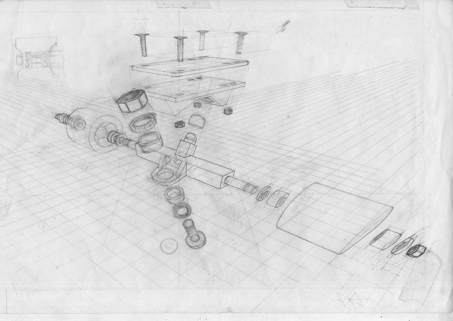
Part 1 base construction by student, Ossian Lundin.
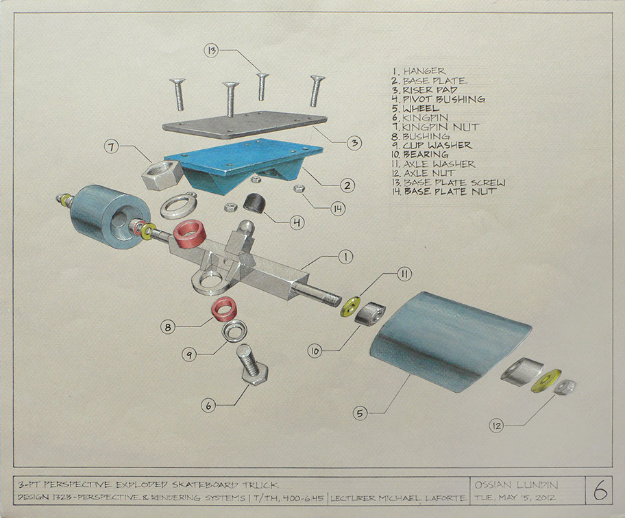
Part 2 finished rendering by student, Ossian Lundin.
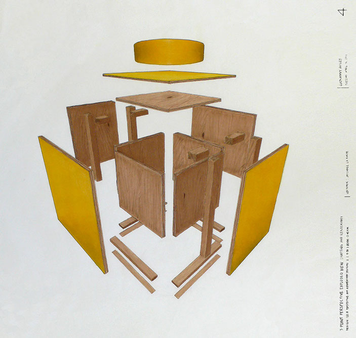
Part 2 finished rendering by student, Giovanny Aviles.
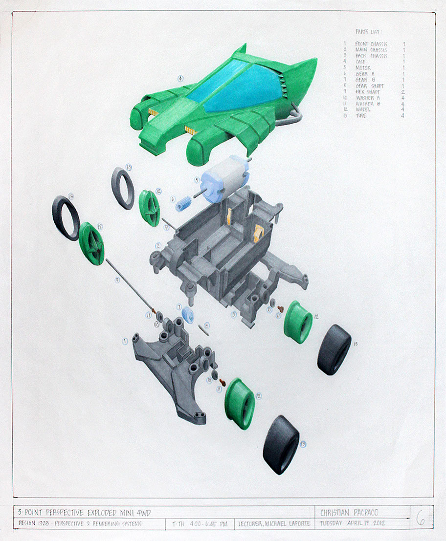
Part 2 finished rendering by student, Christian Pacpaco.
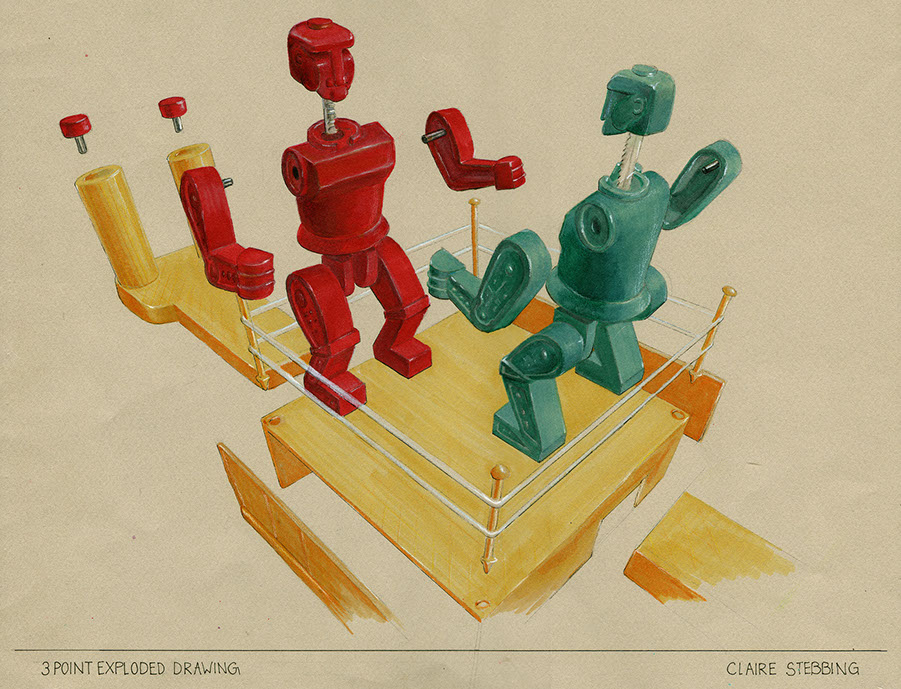
Part 2 finished rendering by student, Claire Stebbing. Fall 2012
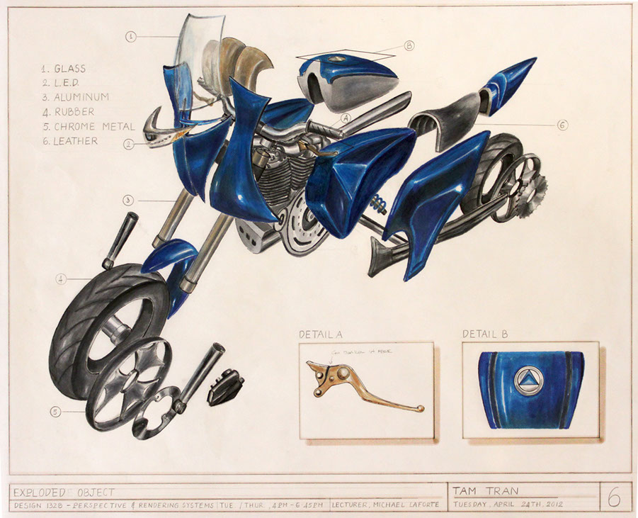
Part 2 finished rendering by student, Tam Tran. Spring 2012
OTHER REFERENCES AND INSPIRATIONS
Example found online. Source unknown. This example employs curvilinear perspective.
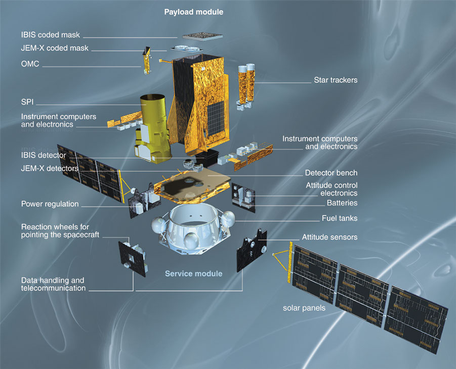
The major components of a satellite.
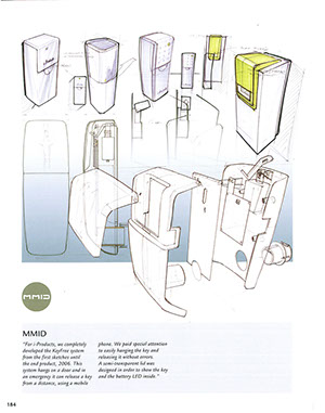
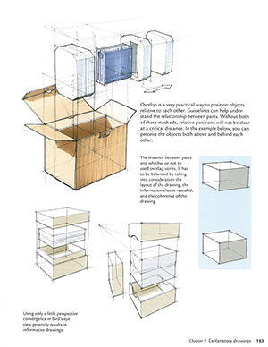
Left: Several examples from the book Sketching by Eissen and Steur. Right: Apple Patented iPhone packaging design schematic.

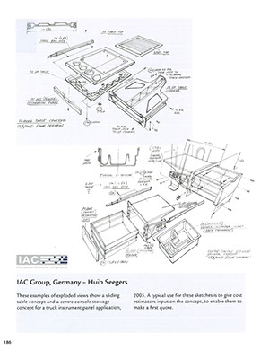
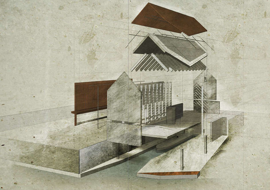
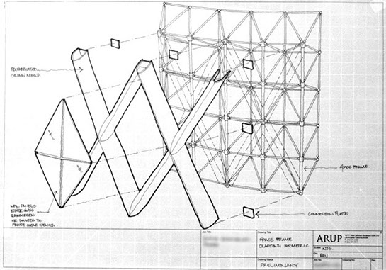
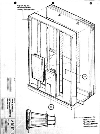
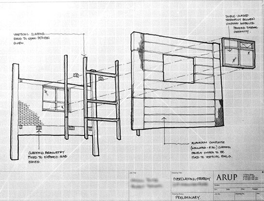
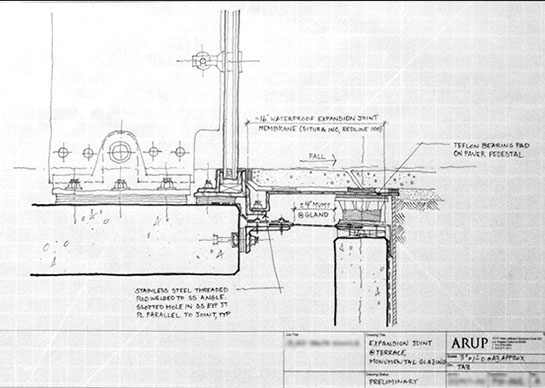
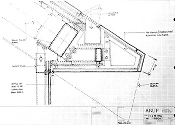
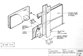
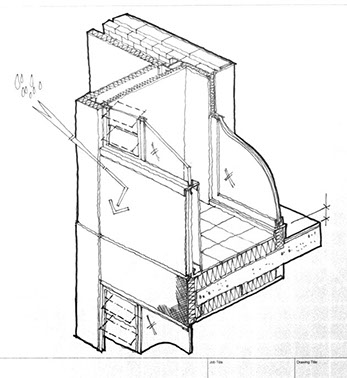
Exploded boat store by Terry Jackson via Architizer. Note this is not in 3-pt Perspective, but is a very good example of an exploded building.
SLOs
STUDENT LEARNING OBJECTIVES
- The ability to gain understanding of how an object or assembly of parts relate to one another,
- Will gain understanding of 3-pt perspective for generating more
dynamic views, - The ability to understand relationships of parts,
- The ability to improvise based upon logic of the system.
GRADING AND EVALUATION RUBRIC
The following Rubric will apply in assessment of the student's work product, presentation, and/or process:

^
* Estimate only. See instructor and calendar for specific due dates. Summer Session schedule is more compressed with one week equal to approximately two and half semester weeks.
CSULB | COTA | DEPARTMENT OF DESIGN | BIO

Questions, feedback, suggestions?
Email me with your recommendations.
©2020 Michael LaForte / Studio LaForte, All Rights Reserved. This site and all work shown here is purely for educational purposes only. Where ever possible student work has been used or original works by Michael LaForte.
Works by professionals found online or in publication are used as instructional aids in student understanding and growth and is credited everywhere possible.