TUTORIALS & HOW-TO GUIDES
As you work, don't worry if your working sheet looks rough as you work through the numbers and understanding the system.
Getting Started
UNDERSTANDING THE MATH AND CONSTRUCTION WITH SLOPE VP
To start, you need to have the beginnings of a 2-story space and know the floor level height you're trying to get to, ie. the Floor-to-Floor height, so block that in early on.
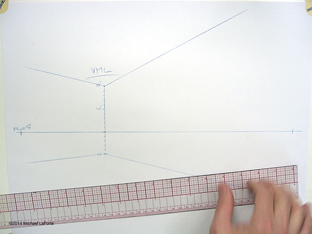
INDICATION OF 2ND FLOOR AT 10'-0"
Calculate the number of steps you need to reach your second floor.
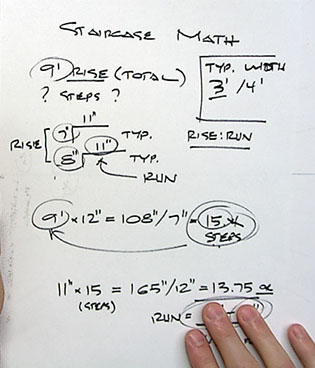
Now you can calculate the number of stairs you will need. You will need to do a little basic math. Watch the math demos below to help you become familiar with working through the math.
INDICATION OF 2ND FLOOR AT 10'-0"
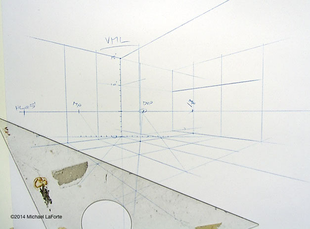
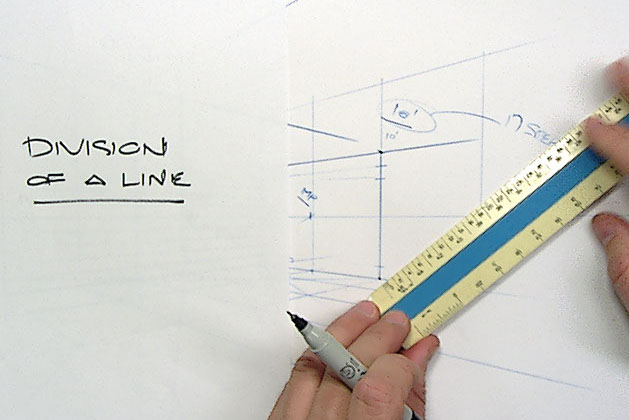
USE THE DIVISION SYSTEM
Use the division system to divide up your vertical "plumb" line into evenly distributed segments based on the number of steps derived in your staircase math.
Staircase Math Example 1. Video available here
Reminder!
Make sure you calculate to the floor level, NOT to the ceiling!
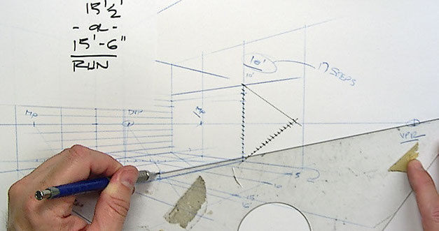
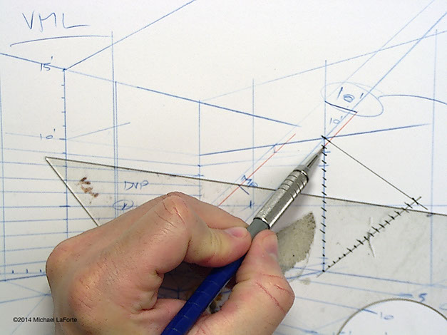
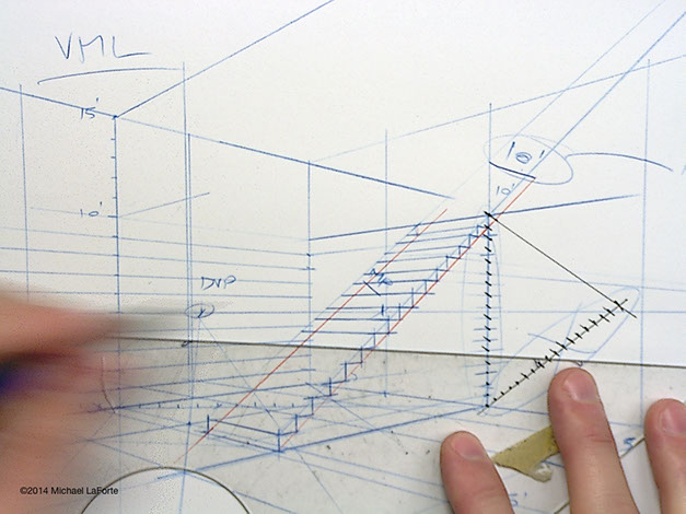
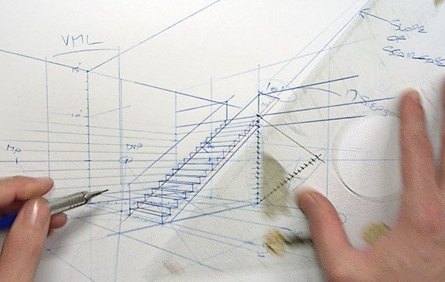
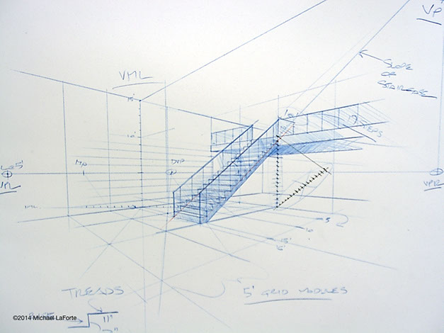
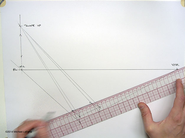
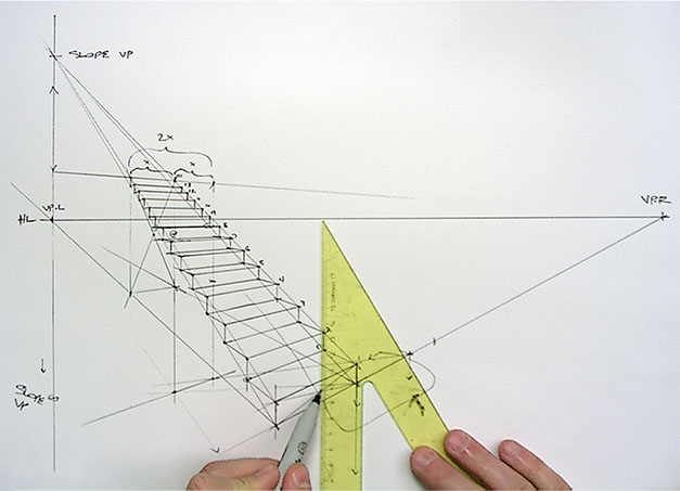
SET THE SLOPE
Plot a line from the first step nose to the final step nose (the actual 2nd Floor). This is your staircase slope.
This slope will intersect a vertical line directly above the corresponding VP.
This intersection is your Slope VP
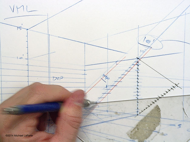
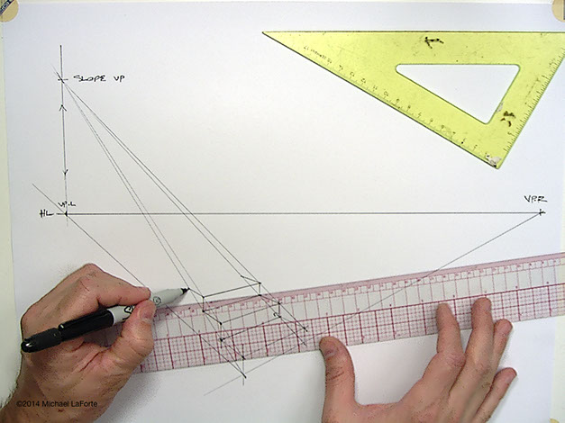
CONTROL LINES
Use the Slope VP to set
4 Control Lines.
Feel free to use different colored pencils to help
you keep track of them.
I like to use Blue for the NOSE lines, and Red for
the lower, Stringer line.
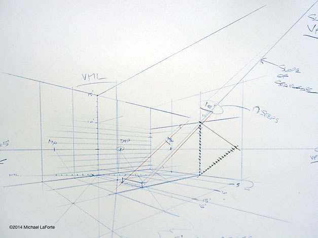
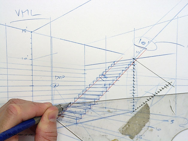
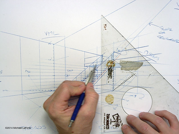
SETTING THE TREADS
Carry the tick marks from your Vertically Divided line, forward from the Native VP (in this image the Right VP), and cross through the upper and lower Control Lines.
Make sure you are working across the same plane, and not jumping across planes.
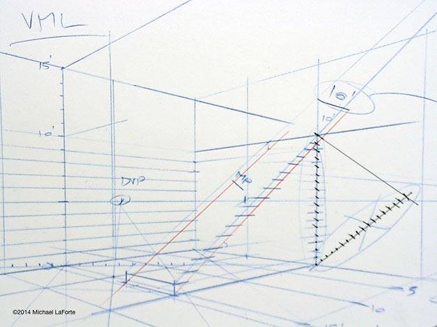
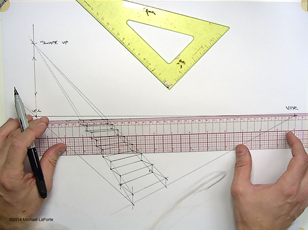
STAIRS RISERS
Draw vertical lines through the intersections of the upper control line to lower control lines at each horizontal tread line. Again, focusing on only the one plane.
It is unlikely that every single intersection aligns vertically perfectly. They should be reasonably close though, unless you've been sloppy in your construction. If you have been careless, you may need to start over and be more precise and disciplined.
Average out any minor discrepencies, distributing your verticals smoothly according to the basic rules of foreshortening—don't tilt your verticals to match the intersections, this will look terrible in the end.
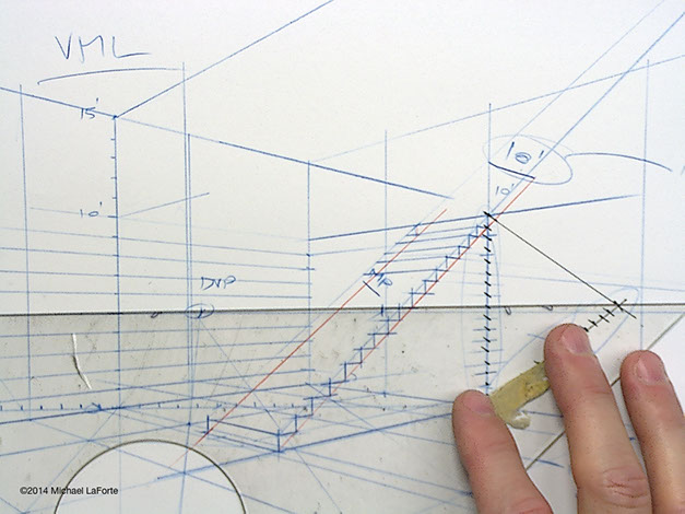
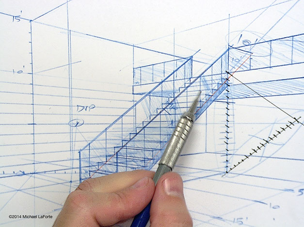
STAIRS NOSES
Using the upper control line corners, carry lines toward the Left VP (in this example), stopping at the far side upper control line.
Repeat this for the lower control line, inside corners.
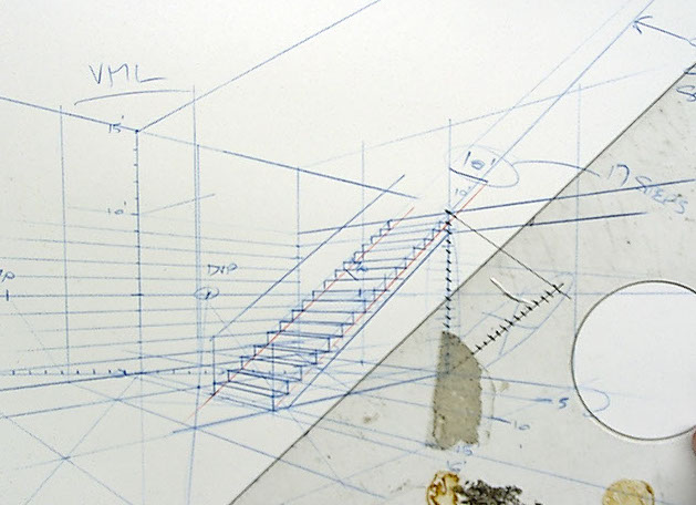
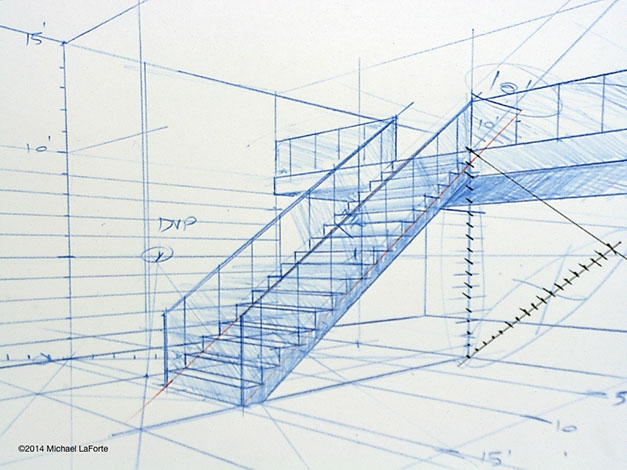
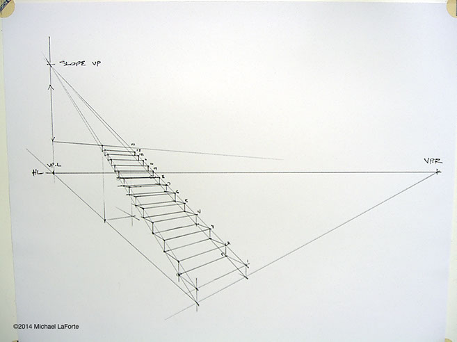
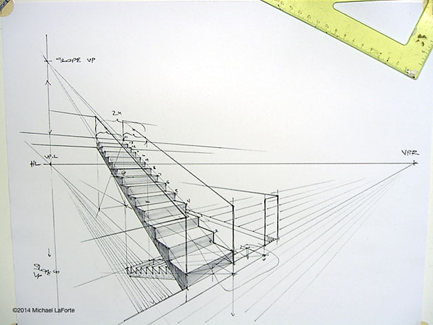
FINISHING
Complete the steps on the far side by striking the vertical edges.
You can now see the stairs foreshorten and converge properly, despite some of the geometry being impossible to map.
The Slope VP and Slope Control Lines have given us a system that keeps everything in order.
ADD HANDRAILS
You can do this easily off the steps. Since a typical handrail is approximately 36" above the floor,
and assuming each step is approximately 7" high, 7 will go into 36, 5.14 times. We can round it
out to 5, that's close enough. Count 5 steps and carry that height forward to the first step.
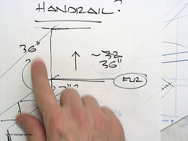
Using the slope Vanishing Point, carry the height up the slope.
As you work, and you start seeing the steps coming together, begin considering the design of your stairs, the materials and how it will be fabricated. Do some research to help you're understanding until you know more about assembly and fabrication methods.
See Marretti Staircases for some very beautifully detailed staircase designs.
STEP-BY-STEP METHOD WITH ESTIMATED SLOPE
A good way to practice is to simply estimate a slope and run length, then build steps one at a time starting from the bottom and working up toward your second floor.
There's nothing wrong with this approach, but be careful of your proportions. All too often I see steps where the rise and tread are too equal. The tread should be about a third longer than the rise.
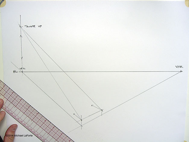
SET THE SLOPE
Plot a line from the first step nose to intersect the vertical line from the corresponding VP (left VP in this example). This is establishes your staircase slope VP.
Use the Slope VP to strike the far side of the staircase slope as well.
CONTROL LINES
Use the Slope VP to set 4 Control Lines. Two upper, Nose, and two lower, Stringer.
Feel free to use different colored pencils to help you keep track of them.
I like to use Blue for the NOSE lines, and Red for the lower, Stringer line.
SETTING THE TREADS AND RISERS
Working from the bottom step nose, step 1, carry a line toward the left VP. When it intersects the lower Slope Control Line, draw a vertical up to the Nose Slope Control Line (the upper slope line), Repeat this process all the way up.
Feel free to connect across to build the width at the same time. This will save you time, and allow you to see the steps emerging.
REPEAT
At the Horizon Line, you may find it difficult to map the geometry, but do your best to maintain the smooth consistency of the steps.
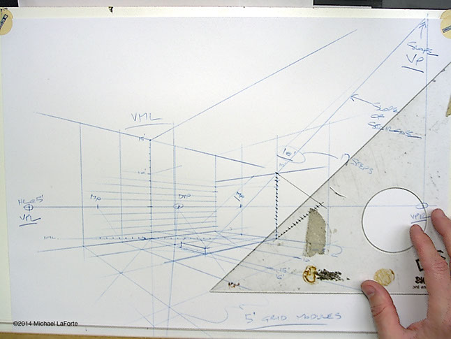
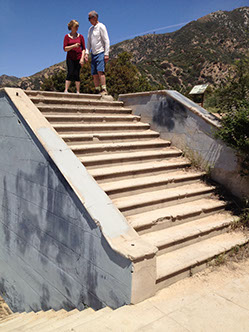
RELATIVE FLOOR HEIGHTS
A typical house or apartment building with an 8' ceiling height will have an approximate floor-to-floor height of 9'-6" to 10'-0", or abut 17 or 18 steps. When you have about 17 or 18 steps, you can set this as your second floor level. If you wanted a taller loft space, add more steps.
Do consider practical codes. After a certain number of steps, we are required to insert a landing.
ADD A LANDING, OR MULTIPLE LEVELS
No matter which method you use, you can create wrapping staircases by continuing up and/or down.
You can get a pretty good estimate of the slope down by measuring the vertical height from the ground plane to loft (green), and vertically double it (blue).
Be sure the slope VP is directly vertically down from the HL VP.
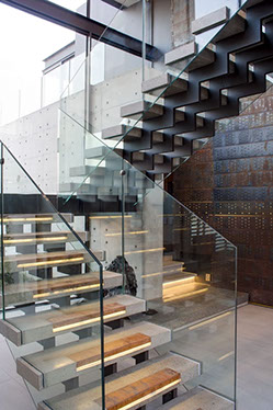
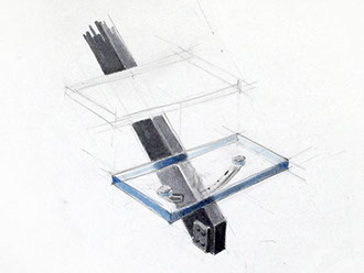
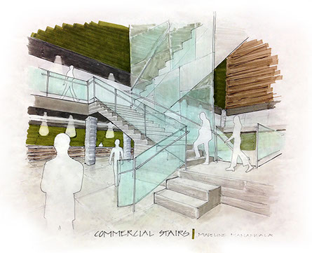
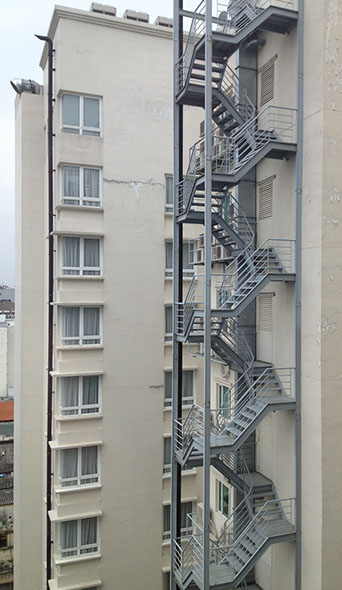
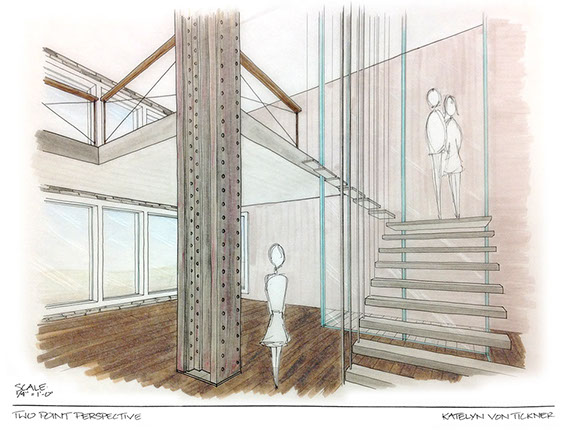
Designing with glass handrails is not only modern and minimalist, but is easily achieved just from the line work. As you can see in the photo above, we mostly observe glass from its edges, not the plane.
The plane of glass catches reflections. Refer to Mirror Reflections & Chrome Logic and Glass Rendering for more guidance.
HL
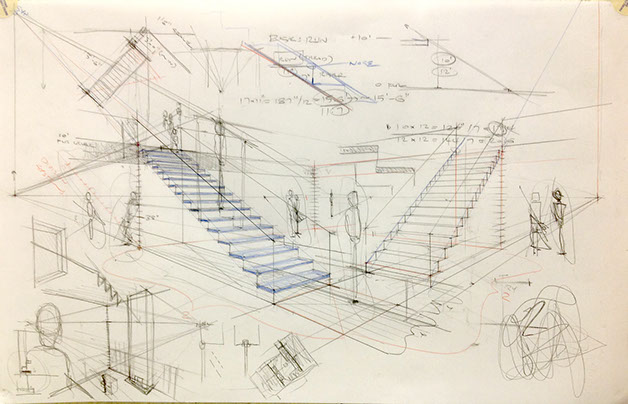
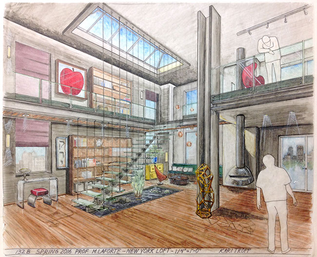
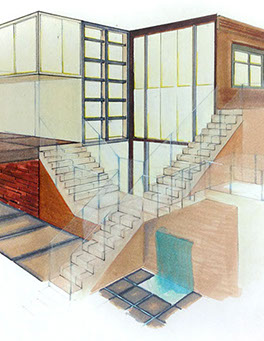
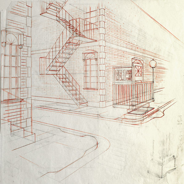
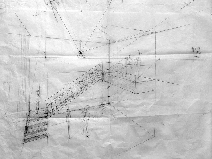
The examples above and below are 2-PT perspectives with a very far distant right VP, and strong concentration toward the center VP. The sketch below is constructed from a view-point on the second floor level with a 15' Horizon Line or Eye Level.

* Estimate only. See instructor and calendar for specific due dates. Summer Session schedule is more compressed with one week equal to approximately two and half semester weeks.
CSULB | COTA | DEPARTMENT OF DESIGN | BIO

Questions, feedback, suggestions?
Email me with your recommendations.
©2020 Michael LaForte / Studio LaForte, All Rights Reserved. This site and all work shown here is purely for educational purposes only. Where ever possible student work has been used or original works by Michael LaForte.
Works by professionals found online or in publication are used as instructional aids in student understanding and growth and is credited everywhere possible.